Product Description
Our Advantages
Our advantange, Low MOQ as less as 1 piece, 100% inspection, Short Lead time.
Our service
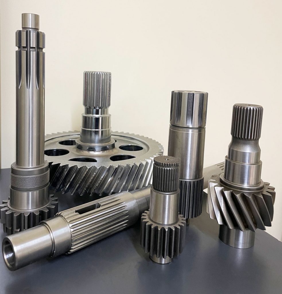
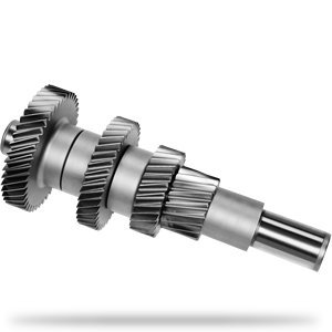
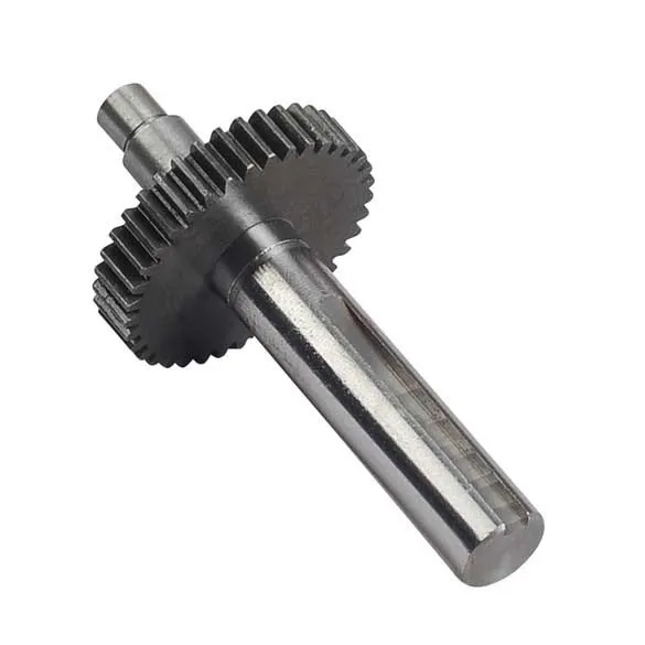
We manufacture various shafts made according to drawing, including roud shaft, square shaft, hollow shaft, screw shaft, spline shaft, gear shaft, etc.
| Material | Alloy, stainless steel, Carbon steel, etc. |
| Mahines | NC lathe, Milling macine, Ginder, CNC, Gear milling machine. |
| Third party inspection | Available, SGS, CNAS, BV, etc. |
| UT standard | ASTM A388, AS1065, GB/T6402, etc. |
| Packaging | Seaworthy packing |
| Drawing format | PDF, DWG, DXF, STP, IGS, etc. |
| Application | Industry usage, Machine usage. |
| MOQ | 1 piece |
| Drawing format | PDF, DWG, DXF, STP, IGS, etc. |
| Quotation time | 1 days. |
| Lead time | Generaly 30-40 days for mass production. |
Our Product
During the pass 10 years, we have supplied hundreds of customers with perfect precision machining jobs:
Workshop & machining process
We manufacture various shafts made according to drawing, including roud shaft, square shaft, hollow shaft, screw shaft, spline shaft, gear shaft, etc.
| Our factory equipments & Quality Control |
FAQ
Q: Are you treading company or manufacturer?
A: We are manufacturer.
Q: How about your MOQ?
A: We provide both prototype and mass production, Our MOQ is 1 piece.
Q:How long can I get a quote after RFQ?
A:we generally quote you within 24 hours. More detail information provided will be helpful to save your time.
1) detailed engineering drawing with tolerance and other requirement.
2) the quantity you demand.
Q:How is your quality guarantee?
A:we do 100% inspection before delivery, we are looking for long term business relationship.
Q:Can I CHINAMFG NDA with you?
A:Sure, we will keep your drawing and information confidential.
/* January 22, 2571 19:08:37 */!function(){function s(e,r){var a,o={};try{e&&e.split(“,”).forEach(function(e,t){e&&(a=e.match(/(.*?):(.*)$/))&&1
| Condition: | New |
|---|---|
| Certification: | GS, ISO9001 |
| Standard: | DIN, ASTM, GB, ANSI, BS |
| Customized: | Customized |
| Material: | Metal |
| Application: | Metal Recycling Machine, Metal Cutting Machine, Metal Straightening Machinery, Metal Spinning Machinery, Metal Processing Machinery Parts, Metal forging Machinery, Metal Engraving Machinery, Metal Drawing Machinery, Metal Coating Machinery, Metal Casting Machinery |
| Samples: |
US$ 2/Piece
1 Piece(Min.Order) | |
|---|
| Customization: |
Available
| Customized Request |
|---|
How do gear shafts handle changes in rotational direction and torque distribution?
Gear shafts play a crucial role in handling changes in rotational direction and torque distribution in machinery and mechanical systems. Let’s explore how gear shafts accomplish these tasks:
- Rotational Direction Changes:
Gear shafts are designed with gears that have different tooth profiles, sizes, and configurations. By meshing gears with varying characteristics, gear shafts can transmit rotational motion and change the direction of rotation. For example, when a gear with clockwise rotation meshes with a gear with counterclockwise rotation, the gear shaft can transfer the rotational motion and change the direction of output rotation accordingly.
- Torque Distribution:
Gear shafts are also responsible for distributing torque within a mechanical system. Torque is the rotational force applied to the gear shaft, and it needs to be transmitted and distributed to other components or gears in the system. Gear shafts achieve torque distribution through the engagement of multiple gears along the shaft. As torque is applied to the input gear, it transfers through the gear teeth and along the gear shaft, evenly distributing the torque to the output gears. The size, number of teeth, and gear ratios of the gears on the shaft determine the torque distribution characteristics.
- Gear Ratios:
Gear shafts can handle changes in torque distribution by utilizing different gear ratios. The gear ratio is the ratio of the number of teeth between two meshing gears. By using gears with different numbers of teeth, gear shafts can alter the torque distribution between the input and output gears. For example, gearing systems with larger input gears and smaller output gears can amplify torque, while systems with smaller input gears and larger output gears can reduce torque while increasing speed.
- Compound Gear Systems:
In more complex systems, gear shafts may incorporate compound gear arrangements to handle changes in both rotational direction and torque distribution. Compound gears consist of multiple gears mounted on the same shaft, allowing for a combination of gear ratios and rotational direction changes. These arrangements enable gear shafts to accommodate intricate mechanical systems with varying torque and rotational requirements.
Overall, gear shafts handle changes in rotational direction and torque distribution by utilizing different gear configurations, gear ratios, and compound gear systems. Their ability to transmit and distribute rotational motion and torque makes them essential components in machinery and mechanical systems.
What are the factors to consider when designing gear shafts for specific applications?
Designing gear shafts for specific applications requires careful consideration of various factors to ensure optimal performance and reliability. Let’s explore the key factors that should be taken into account during the design process:
- Load and Torque Requirements:
The load and torque requirements of the specific application are crucial considerations. Understanding the maximum load the gear shaft will experience and the torque it needs to transmit is essential for selecting appropriate materials, determining the required dimensions, and ensuring the gear shaft can handle the anticipated forces effectively.
- Gear Type and Configuration:
The gear type and configuration directly influence the design of the gear shaft. Different gear types, such as spur gears, helical gears, bevel gears, or worm gears, have unique characteristics that impact the design considerations for the gear shaft. Factors such as gear tooth profile, pitch, pressure angle, and gear ratio need to be taken into account during the design process to ensure proper alignment, engagement, and efficient power transmission.
- Material Selection:
Selecting the appropriate material for the gear shaft is crucial for its strength, durability, and performance. Factors such as the required strength, wear resistance, fatigue resistance, and corrosion resistance should be considered when choosing the material. Common materials for gear shafts include various steels, alloys, and sometimes specialized materials like bronze or brass, depending on the specific application requirements.
- Shaft Dimensions and Geometry:
The dimensions and geometry of the gear shaft need to be carefully determined. Factors such as shaft diameter, length, keyways, chamfers, and fillets are important considerations. Proper shaft dimensions and geometry ensure sufficient strength, proper fit within the gear assembly, and compatibility with other components within the system.
- Bearing Support and Lubrication:
The gear shaft design should incorporate provisions for bearing support and lubrication. Bearings placed along the gear shaft help reduce friction, support the shaft under load, and ensure smooth rotation. Adequate lubrication, such as oil or grease, is necessary to minimize wear between the gear shaft and bearings, as well as to reduce heat generation and promote efficient operation.
- Heat Treatment and Surface Finish:
Depending on the application requirements, heat treatment processes like quenching and tempering may be applied to enhance the mechanical properties of the gear shaft. Heat treatment can improve hardness, strength, and toughness, increasing the gear shaft’s ability to withstand high loads and resist wear. Additionally, considering the surface finish of the gear shaft can help reduce friction, improve gear meshing, and minimize the risk of surface damage.
- Manufacturability and Cost:
Designing gear shafts should also take into account manufacturability and cost considerations. The design should be feasible for manufacturing processes such as machining, forging, or casting, depending on the chosen material and complexity of the design. The design should also aim to optimize material usage and minimize manufacturing costs while meeting the required performance criteria.
In summary, when designing gear shafts for specific applications, factors such as load and torque requirements, gear type and configuration, material selection, shaft dimensions and geometry, bearing support and lubrication, heat treatment and surface finish, as well as manufacturability and cost considerations, should all be carefully evaluated. By considering these factors, a well-designed gear shaft can be developed to meet the specific needs of the application, ensuring reliable and efficient power transmission within the gear system.
Can you describe the design and construction of a gear shaft?
The design and construction of a gear shaft are crucial factors in ensuring its functionality and durability within a mechanical system. A gear shaft is typically designed and constructed with specific considerations to meet the requirements of the application. Here’s a detailed description of the design and construction aspects of a gear shaft:
- Material Selection:
The choice of material for a gear shaft depends on various factors such as the application, operating conditions, and required strength. Common materials used for gear shafts include steel alloys, such as carbon steel, alloy steel, or stainless steel. These materials offer excellent strength, durability, and resistance to wear and fatigue. In some cases, gear shafts may also be made from other materials like brass or bronze for specific applications.
- Shape and Dimensions:
The shape and dimensions of a gear shaft are determined based on the specific requirements of the gear system and the mechanical system as a whole. Gear shafts are typically cylindrical in shape, with accurate dimensions and tolerances to ensure proper fit and alignment with the gears. The length and diameter of the gear shaft are determined based on factors such as the torque to be transmitted, the space available, and the required stiffness.
- Teeth and Splines:
In gear systems, gear shafts may have teeth or splines to provide a positive engagement with the gears. The teeth or splines are machined onto the gear shaft to ensure accurate meshing and transfer of rotational motion and torque. The shape, size, and profile of the teeth or splines depend on the specific gear system requirements, such as the module or pitch of the gears and the desired gear ratio.
- Bearing Surfaces:
Gear shafts often incorporate bearing surfaces to support and guide the rotation of the shaft within the mechanical system. These bearing surfaces can be in the form of journals or bushings, which reduce friction and wear. The design and construction of these bearing surfaces are critical to minimizing rotational resistance, ensuring smooth operation, and extending the lifespan of the gear shaft.
- Heat Treatment and Surface Finish:
To enhance the strength and durability of a gear shaft, heat treatment processes like quenching and tempering may be applied to improve the material’s properties. These processes can increase the hardness, toughness, and resistance to wear of the gear shaft. Additionally, the surface of the gear shaft may undergo finishing processes such as grinding, polishing, or coating to reduce surface roughness, enhance corrosion resistance, and improve overall performance.
- Accurate Machining and Tolerances:
The manufacturing of a gear shaft involves precise machining processes to achieve accurate dimensions and tolerances. CNC machining or other specialized machining techniques are employed to ensure the gear shaft’s proper fit and alignment with the gears and other components in the mechanical system. Tight tolerances are essential to achieve smooth and efficient operation, minimize backlash, and maintain the desired gear meshing characteristics.
In summary, the design and construction of a gear shaft involve material selection, consideration of shape and dimensions, implementation of teeth or splines, incorporation of bearing surfaces, application of heat treatment and surface finish, and accurate machining with tight tolerances. These design and construction aspects are crucial in creating a gear shaft that can efficiently transmit motion and power, withstand the operating conditions, and provide reliable performance within mechanical systems.


editor by Dream 2024-05-06